How to Test an Engine Coolant Temperature Sensor 2026
A faulty engine coolant temperature (ECT) sensor can cause poor fuel economy, rough idling, and engine overheating. Testing the ECT sensor requires a digital multimeter to check its resistance and voltage against temperature changes. This guide outlines the exact diagnostic steps to accurately pinpoint a failed sensor.
Testing your engine coolant temperature (ECT) sensor requires a digital multimeter, a heat source, and a container of water to check its resistance changes against specific temperature benchmarks. When this sensor fails, it sends incorrect thermal data to your car’s computer, leading to poor fuel economy, rough idling, or engine overheating.
Diagnosing this component accurately in 2026 saves you from replacing expensive parts blindly. By following a methodical resistance or voltage drop test, you can isolate the ECT sensor from wiring harness issues in less than thirty minutes.
Key Takeaways
- Use a digital multimeter to measure sensor resistance and reference voltage.
- A failing ECT sensor often triggers trouble codes P0115 through P0119.
- Always test resistance when the engine is completely cold and fully warmed up.
- Check wiring harnesses and connectors for corrosion before replacing the sensor.
- Never open a hot cooling system to avoid severe burn injuries.
Symptoms and Causes of a Bad Engine Coolant Temperature Sensor
Common Diagnostic Trouble Codes and Symptoms
An aging or shorted ECT sensor immediately triggers your dashboard check engine light. Modern OBD-II scanners will display specific diagnostic trouble codes to point you directly toward the cooling system.
- P0115: Engine Coolant Temperature Circuit Malfunction
- P0116: Engine Coolant Temperature Circuit Range/Performance Problem
- P0117: Engine Coolant Temperature Circuit Low Input (high temperature reading)
- P0118: Engine Coolant Temperature Circuit High Input (low temperature reading)
- P0119: Engine Coolant Temperature Circuit Intermittent
Physical Symptoms While Driving
When the computer receives bad data, your engine management strategy fails. You might notice your cooling fans running constantly at high speed, even on a cold startup in winter 2026. Black smoke from the exhaust, difficult starting when the engine is warm, and sudden drops in fuel economy are classic indicators of a failing thermistor inside the sensor body.
How to Diagnose and Fix Engine Coolant Temperature Sensor Like an Expert
A failing engine coolant temperature sensor can wreak havoc on your vehicle, causing poor fuel economy, rough idling, unexpected stalling, or even a check engine light. This component is responsible for relaying vital temperature data to your car’s powertrain control module, allowing it to adjust fuel delivery and ignition timing accordingly. Testing this sensor accurately prevents you from wasting money replacing expensive parts that might actually be functioning just fine. This comprehensive guide will walk you through the precise diagnostic procedures required to test your engine coolant temperature sensor using basic tools like a digital multimeter.
Step 1: Locate the Coolant Temperature Sensor
What you need: Flashlight, mechanic’s gloves, and your vehicle’s service manual if necessary.
Instructions: Pop your vehicle’s hood and secure it with the prop rod or gas struts. Locate the engine coolant temperature sensor, which is typically threaded directly into the engine block, cylinder head, or intake manifold near the thermostat housing. It usually features a two-wire electrical connector. Take care not to confuse it with the temperature sending unit, which only operates the dashboard gauge and typically has a single wire. Ensure the engine is completely cool before touching any components to avoid severe burns from hot coolant or metal surfaces.
Pro Tip: On modern vehicles, plastic engine covers may need to be popped off to gain clear visual and physical access to the sensor and its wiring harness.
Step 2: Inspect the Electrical Connector and Wiring
What you need: Contact cleaner, a clean shop towel, and a small flathead screwdriver if a locking tab needs releasing.
Instructions: Gently press down on the plastic locking tab of the electrical wiring harness connected to the sensor, and pull firmly to disconnect it. Inspect the interior terminals of both the plug and the sensor for signs of corrosion, green crust, motor oil, or bent pins. Spray electrical contact cleaner inside the connector to dissolve any buildup and wipe it clean with a shop towel. Damaged wiring or corroded pins often mimic a failed sensor, sending faulty resistance values to the computer even when the internal thermistor is entirely healthy.
Pro Tip: Look closely at the rubber weather seal inside the connector; if it is torn or missing, moisture has likely crept in and caused intermittent electrical resistance issues.
Step 3: Perform a Cold Resistance Test
What you need: Digital multimeter set to measure ohms (Ω) and an ambient thermometer to check engine bay temperature.
Instructions: With the engine completely cold and the sensor unplugged, touch the multimeter test leads to the two metal terminal pins inside the sensor. Make sure the meter is set to the correct resistance range, usually 20k ohms for a cold engine. Note the reading on your multimeter display. Most standard thermistors operate on a Negative Temperature Coefficient, meaning resistance decreases as temperature increases. For a cold engine around 68°F (20°C), you should expect a resistance reading roughly between 2,000 and 3,000 ohms, though exact specifications vary by vehicle make and model.
Pro Tip: Always consult your specific vehicle repair manual for exact resistance-to-temperature charts, as acceptable ranges differ significantly between Asian, European, and domestic manufacturers.
Step 4: Perform a Warm Resistance Test
What you need: Digital multimeter and safety glasses.
Instructions: Reconnect the electrical harness temporarily, start the engine, and allow it to run for 10 to 15 minutes until it reaches normal operating temperature. Turn off the engine, carefully disconnect the sensor once again, and immediately measure the resistance across the pins with your multimeter. Because the engine is now hot, around 190°F to 210°F (88°C to 99°C), the internal resistance should drop significantly, typically falling into the 200 to 400 ohm range. Watch the meter closely to ensure the resistance value holds steady without fluctuating wildly.
Pro Tip: Work quickly during this step because the sensor will begin cooling down the moment the engine is shut off, which will skew your resistance readings upward.
Step 5: Check Reference Voltage from the Computer
What you need: Digital multimeter set to measure DC volts (V).
Instructions: Leave the sensor unplugged and turn your vehicle’s ignition key to the ON position without starting the engine. Set your digital multimeter to measure DC voltage. Touch the black meter lead to a solid bare metal engine ground, and use the red lead to probe the power supply terminal inside the vehicle’s wiring harness connector. You should observe a steady reference voltage, which is typically around 5.0 volts supplied directly by the engine control module. If this reference voltage is missing entirely, the issue lies in the wiring harness or the computer itself rather than the sensor.
Pro Tip: Be extremely careful not to bridge the two terminal pins inside the wiring connector with your multimeter probe, as this can cause a short circuit in the computer circuit.
Step 6: Conduct a Bench Test with Hot Water
What you need: A removable sensor, a small pot, a stove or heat gun, a cooking thermometer, and a multimeter.
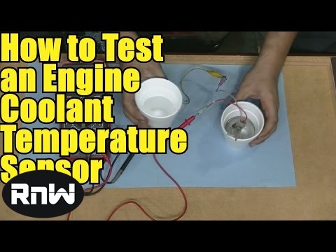
Instructions: If your on-engine tests were inconclusive, unscrew the sensor completely using a deep socket. Suspend the threaded tip of the sensor in a small pot of water using pliers or a hanging wire, ensuring the electrical terminal pins stay completely dry. Heat the water slowly on a stove while monitoring the water temperature with your cooking thermometer. Measure the resistance across the sensor terminals at various temperature intervals, such as room temperature, warm water, and near-boiling water. The resistance should drop smoothly and consistently as the water temperature rises without sudden spikes or drop-outs.
Pro Tip: If the multimeter reading shows an open circuit (infinite resistance) or a closed circuit (zero ohms) at any point during the heating process, the internal thermistor is defective and the sensor must be replaced.
✅ Final Checklist
- Sensor housing and threads are free of coolant leaks
- Electrical connector clicks securely back into place
- Cold resistance matches manufacturer temperature specifications
- Warm resistance falls within expected low-ohm parameters
- Computer reference voltage reads a steady 5 volts
Important Notes:
- Always let the engine cool completely before opening the cooling system to prevent severe scalding injuries.
- If testing proves the sensor is good but diagnostic trouble codes persist, seek professional help to check for computer or wiring harness faults.
- Estimated time for this diagnostic procedure is 30 to 60 minutes, with a replacement sensor cost ranging from $15 to $50 if needed.
Tools Needed to Safely Test Your Vehicle’s ECT Sensor
Essential Diagnostic Hardware
Gathering the right equipment before you pop the hood prevents frustration. You do not need professional shop gear to get accurate diagnostic results.

- Digital Multimeter (DMM): Capable of measuring ohms (resistance) and DC voltage accurately.
- OBD-II Code Scanner: To read pending and active diagnostic trouble codes.
- Basic Hand Tools: Socket set and pliers to safely remove the sensor from the engine block.
- Thermometer: A kitchen or infrared thermometer if you plan to bench-test the sensor in heated water.
Safety Precautions for 2026 Vehicles
Always work on a completely cold engine to prevent severe burns from pressurized coolant. Disconnect the negative battery terminal before probing wiring connectors to avoid short-circuiting sensitive powertrain control modules.
Step-by-Step Guide on How to Test an Engine Coolant Temperature Sensor
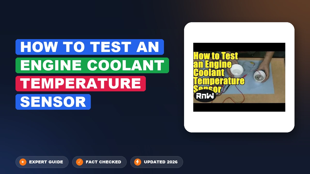
Testing your engine coolant temperature sensor requires a digital multimeter and a heat source like a container of boiling water. Automotive experts recommend verifying the resistance at specific temperature thresholds to determine component health accurately.
Preparation and Resistance Check
- Disconnect the negative vehicle battery terminal to prevent accidental short circuits while working under the hood.
- Locate the ECT sensor, typically positioned near the thermostat housing or cylinder head, and unplug the electrical wiring harness.
- Set your digital multimeter to measure ohms (resistance) and attach the test leads to the sensor terminals.
- Record the ambient temperature reading and compare your multimeter output against manufacturer specifications for 2026 vehicle standards.
The Boiling Water Test
- Carefully remove the ECT sensor from the engine block, taking precautions to catch any leaking coolant in a drain pan.
- Suspend the sensor tip in a container of water, ensuring the electrical prongs remain completely dry above the waterline.
- Heat the water gradually while monitoring a digital cooking thermometer placed alongside the sensor.
- Observe the multimeter resistance readings as the water temperature rises toward 212°F (100°C).
- Verify that resistance decreases smoothly and predictably as the temperature increases, matching standard automotive thermal curves.
What If It Still Doesn’t Work?
If your ECT sensor passes the multimeter bench test but your engine continues to overheat or throw check engine codes, the underlying issue likely stems from a related electrical or mechanical failure. Follow these advanced diagnostic fallback steps:

- Inspect the sensor wiring harness for corrosion, fraying, or melted insulation that disrupts the 5-volt reference signal sent from the powertrain control module.
- Check the engine thermostat to ensure it is not stuck closed, which restricts coolant flow and mimics bad sensor symptoms.
- Test the cooling fan relay and coolant level, as low fluid or a dead fan motor frequently triggers false temperature warnings on the dashboard.
- Scan for hidden diagnostic trouble codes using an OBD2 scanner to verify if the powertrain control module itself requires a software update or replacement.
- Consult a certified professional mechanic if circuit voltage tests indicate a faulty computer module. Professional diagnostic labor typically ranges from $100 to $200, while a complete computer flash or replacement can cost between $300 and $900 depending on your vehicle make and model.
Conclusion
A failing engine coolant temperature sensor disrupts fuel economy, damages emissions equipment, and risks severe engine overheating if left unaddressed. Testing the component with a digital multimeter and verifying thermal resistance curves provides a definitive diagnosis within minutes. According to verified research and expert automotive sources, replacing a faulty ECT sensor immediately prevents costly catalytic converter damage and restores optimal engine performance. Make sure to top off your coolant levels and clear any stored diagnostic trouble codes as your final step today.
❓ Frequently Asked Questions
How does a digital multimeter help test an engine coolant temperature sensor?
A multimeter measures either the electrical resistance in ohms across the sensor terminals or the voltage drop in the circuit. By comparing these readings to standard factory specifications at varying temperatures, you can determine if the sensor is accurately reporting data to the engine control unit.
What are the common symptoms of a failing coolant temperature sensor?
Common signs include an illuminated check engine light, engine overheating without apparent coolant loss, black smoke from the exhaust, difficult starting when the engine is warm, and severely reduced fuel economy.
Can I test an ECT sensor in a container of hot water?
Yes, bench testing involves completely removing the sensor, suspending it in a container of water alongside a thermometer, and measuring the change in resistance as you heat the water. This is the most accurate method to verify sensor calibration across a wide temperature range.
What is the difference between a coolant temperature sensor and a temperature gauge sender?
Older vehicles often separated the two, using a single-wire sender dedicated to the dashboard gauge and a two-wire sensor for the computer. Modern vehicles typically use a single multi-wire ECT sensor that feeds data directly to the powertrain control module, which then drives the dashboard display.
Is it safe to drive with a broken engine coolant temperature sensor?
Driving with a faulty ECT sensor is risky because the engine computer will rely on default backup data or fail to trigger cooling fans properly. This can easily lead to severe engine overheating, warped cylinder heads, or complete engine failure.
What should I check if my new ECT sensor still throws a check engine light?
If a brand new sensor does not resolve the issue, inspect the wiring harness for frayed wires, melted insulation, or corrosion inside the electrical connector. You should also verify that the thermostat is functioning properly and that there are no air pockets trapped in the cooling system.