How to Tell If Throttle Position Sensor is Bad Expert 2027
A malfunctioning throttle position sensor (TPS) can cause various drivability issues. This guide provides clear symptoms and expert diagnostic steps, including multimeter and OBD-II testing, to help you accurately identify a bad TPS and restore your vehicle’s performance.
Directly confirming a malfunctioning Throttle Position Sensor (TPS) typically involves observing specific engine behavior combined with precise diagnostic testing. You’ll need to look for a cluster of symptoms rather than just one, then validate your suspicions with an OBD-II scanner’s live data or a multimeter. Properly identifying a faulty TPS prevents unnecessary part replacements and ensures your vehicle’s engine management system receives accurate data, which is critical for optimal performance and fuel efficiency in 2027’s increasingly complex automotive landscape.
This isn’t just about fixing a check engine light; it’s about restoring smooth engine operation and preventing potential damage from incorrect fuel-air mixture or erratic transmission shifts. Understanding these diagnostic steps allows you to pinpoint the problem yourself, saving time and money, and avoiding guesswork when your vehicle starts acting up and you suspect the TPS.
Key Takeaways
- Erratic idle, hesitation are key TPS symptoms.
- Use multimeter or OBD-II for accurate TPS diagnosis.
- Fluctuating voltage or no change indicates bad TPS.
- Always check wiring before replacing the sensor.
- Diagnose bad TPS early to prevent further issues.
What Causes TPS Problems: Recognizing the Symptoms
A failing TPS directly impacts your vehicle’s Engine Control Unit (ECU) by sending incorrect signals about your throttle input. This misinformation leads to a range of noticeable and often frustrating symptoms that can significantly degrade your driving experience and even pose safety risks.
Erratic Engine Behavior
- Rough or Fluctuating Idle: When the TPS sends inconsistent signals at idle, the ECU struggles to maintain a steady engine speed. You might notice the RPMs jumping up and down without you touching the pedal, or the engine may sound like it’s struggling to stay on.
- Hesitation or Surging During Acceleration: As you press the accelerator, a bad TPS might either fail to register the change quickly enough (hesitation) or send a signal that’s too high, causing the engine to rev unexpectedly (surging). This can make driving unpredictable and jerky, particularly noticeable at low speeds or when merging onto traffic.
- Sudden Engine Stalling: If the TPS signal abruptly drops or disappears, the ECU might interpret this as the throttle being closed, cutting fuel or spark and causing the engine to stall unexpectedly, especially when coming to a stop or changing gears.
- Difficulty Starting: An incorrect TPS signal can confuse the ECU about the starting fuel requirements, making the engine crank longer or fail to catch. The system might think the throttle is open when it’s closed, or vice-versa.
Transmission and Performance Issues
- Hard Shifting or Delayed Shifts: Modern transmissions rely heavily on TPS data to determine the optimal shift points. A faulty TPS can cause the transmission to shift harshly, hold gears for too long, or shift too early, leading to a noticeable jolt or sluggish performance.
- Reduced Fuel Economy: An ECU receiving bad TPS data might over-fuel or under-fuel the engine, leading to an inefficient combustion process. This directly translates to more frequent trips to the fuel pump as your engine consumes more fuel than necessary.
- Check Engine Light (CEL) Illumination: While not a symptom of how the car feels, the CEL is a critical indicator. The ECU is often programmed to detect implausible TPS signals, triggering a diagnostic trouble code (DTC) such as P0120, P0121, P0122, or P0123. This is your first alert that something is amiss with the throttle position sensor circuit.
- Cruise Control Malfunction: Since cruise control systems precisely manage throttle input to maintain speed, a bad TPS will prevent it from functioning correctly, or cause it to disengage unexpectedly. The system cannot trust the throttle position data it’s receiving.
How to Diagnose and Fix Your Throttle Position Sensor Like an Expert
The Throttle Position Sensor (TPS) is a crucial component in your vehicle’s engine management system. It’s an electrical sensor that monitors the position of the throttle valve and sends this information to the Engine Control Unit (ECU). The ECU then uses this data to calculate the correct fuel injection and ignition timing. A faulty TPS can lead to a host of performance issues, from poor fuel economy and erratic idling to stalling and hesitation. This comprehensive guide will walk you through the essential steps to accurately diagnose a bad TPS, saving you time, money, and frustration. By following these practical instructions, you’ll be able to confidently identify whether your TPS is the culprit behind your car’s troubles.
Step 1: Understand the Symptoms of a Failing TPS
What you need: Your vehicle, a keen awareness of your car’s driving behavior.
Instructions: Before diving into diagnostic tests, familiarize yourself with the common indicators of a failing TPS. These often include an erratic or fluctuating idle speed, engine hesitation or stumbling during acceleration, poor acceleration response, unexpected stalling, or a “check engine” light illuminated on your dashboard. You might also notice poor fuel economy or the vehicle staying in ‘limp mode’ with limited power. Pay close attention to when these symptoms occur – do they happen during initial startup, while driving at certain speeds, or during specific throttle inputs? Documenting these observations will help confirm your diagnosis later.
Pro Tip: While these symptoms strongly suggest a TPS issue, they can also indicate problems with other sensors (like the MAF or O2 sensor) or vacuum leaks. Keep an open mind, but prioritize the TPS if multiple symptoms align with its function.
Step 2: Locate the Throttle Position Sensor (TPS)
What you need: Your vehicle’s owner’s manual or a service manual, a flashlight (optional), basic familiarity with engine bay components.
Instructions: The TPS is typically mounted directly on the throttle body of your engine. The throttle body is usually located between the air intake hose (coming from the air filter box) and the intake manifold. The TPS itself is a small, plastic or metal component with an electrical connector (usually 3 wires) protruding from it, often resembling a small black box or D-shaped sensor. Consult your vehicle’s owner’s manual or an online service diagram for its exact location and appearance. Once identified, ensure the engine is off and cool before proceeding.
Pro Tip: Before disconnecting anything, take a clear photograph of the sensor and its electrical connector. This serves as a reference for reassembly and helps ensure all wires are connected correctly.
Step 3: Perform a Visual Inspection
What you need: Flashlight, clean rags, electrical contact cleaner (optional), small flathead screwdriver (for connector clip, if needed).
Instructions: With the TPS located, visually inspect it for any obvious signs of damage. Look for cracks in the sensor housing, bent or corroded pins on the electrical connector, or frayed wiring. Gently wiggle the connector to ensure it’s securely attached. If there’s any visible dirt, oil, or corrosion on the connector pins, carefully disconnect it (if it has a release tab) and use electrical contact cleaner to clean both the sensor and harness sides. Reconnect the connector firmly, ensuring it clicks into place. Any physical damage or loose connections can lead to intermittent readings.
Pro Tip: Never force a connector. Most automotive connectors have a specific release tab or squeeze clip. Forcing it can break the plastic housing or pins, creating a new, more difficult problem.
Step 4: Check for Diagnostic Trouble Codes (DTCs)
What you need: An OBD-II scanner (either a basic code reader or a more advanced scan tool).
Instructions: Connect your OBD-II scanner to the diagnostic port (typically located under the dashboard on the driver’s side). Turn the ignition key to the “ON” position (engine off). Read any stored or pending Diagnostic Trouble Codes (DTCs). Specifically, look for codes in the P0120-P0124 range, which are generic codes related to the Throttle Position Sensor/Switch “A” Circuit. Your vehicle might also have manufacturer-specific codes related to the TPS. Even if the check engine light isn’t on, sometimes pending codes can indicate an intermittent issue.
Pro Tip: Always note down any codes you find before clearing them. Clearing codes without fixing the underlying issue only resets the check engine light temporarily and can erase valuable diagnostic data.
Step 5: Test the TPS Voltage Output (Static Check)
What you need: Digital Multimeter (DMM) capable of reading DC Volts, a wiring diagram for your specific vehicle (highly recommended), back-probe pins or thin wires.
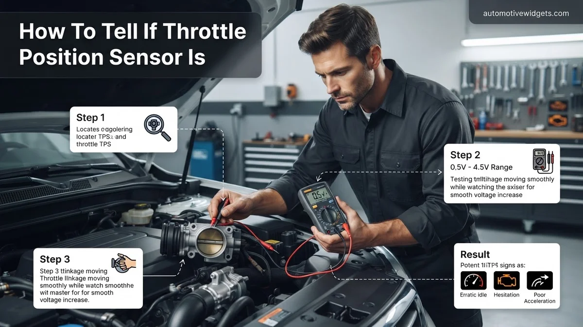
Instructions: With the ignition key in the “ON” position (engine OFF), the TPS needs to be connected to the harness for this test. Using a wiring diagram, identify the signal wire (output), the 5-volt reference wire, and the ground wire of the TPS. Carefully back-probe the signal wire with the positive lead of your DMM and connect the negative lead to a known good ground on the engine chassis or the TPS ground wire. At idle throttle position, the voltage should typically read between 0.5 and 1.0 volts. This static reading confirms the TPS is receiving power and sending an initial signal.
Pro Tip: Always back-probe connections to avoid damaging wire insulation. Piercing wires can lead to future corrosion and electrical issues. If you don’t have back-probe pins, carefully slide a thin, uninsulated wire alongside the sensor pin into the connector.
Step 6: Test the TPS Voltage Output (Dynamic Sweep Check)
What you need: Digital Multimeter (DMM), assistant (optional), back-probe pins.
Instructions: Keep your DMM connected to the TPS signal wire as in Step 5 (ignition “ON,” engine OFF). Slowly open the throttle by hand (or have an assistant slowly press the accelerator pedal). Observe the voltage reading on your DMM. As the throttle plate opens, the voltage should smoothly and linearly increase from its idle value (0.5-1.0V) to approximately 4.5-5.0 volts at Wide Open Throttle (WOT). Look for any sudden drops, spikes, erratic jumps, or flat spots in the voltage reading during the sweep. A smooth, consistent increase is indicative of a healthy TPS.
Pro Tip: A DMM with a graphing function (min/max record or oscilloscope mode) provides the best visual representation of the sweep, making intermittent drops or spikes much easier to identify than just watching numbers on a standard DMM.
Step 7: Confirm 5V Reference and Ground
What you need: Digital Multimeter (DMM), back-probe pins, wiring diagram.
Instructions: If your TPS voltage output tests (Steps 5 & 6) indicate an issue, it’s crucial to ensure the TPS itself is receiving proper power and ground. With the ignition “ON” and the TPS still connected (back-probed), measure the voltage between the 5-volt reference wire and the ground wire. You should see approximately 5.0 volts. If this voltage is absent or incorrect, the problem lies with the vehicle’s wiring or the ECU, not necessarily the TPS itself. Also, measure the continuity between the ground wire and a known good chassis ground (DMM in resistance/ohm mode, should read very close to 0 ohms). A poor reference voltage or ground connection will prevent the TPS from functioning correctly.
Pro Tip: A common mistake is to assume a bad sensor when the power supply or ground circuit is at fault. Always verify these fundamental electrical connections before condemning the sensor itself.
Step 8: Utilize OBD-II Live Data for TPS Percentage
What you need: Advanced OBD-II scanner with live data streaming capability.
Instructions: Connect your advanced OBD-II scanner and navigate to the live data stream function. Look for parameters related to “Throttle Position Sensor Percentage” or “TPS %.” With the ignition “ON” (engine off or running, depending on scanner capability and vehicle) observe the displayed percentage. At idle, it should be a low single digit (e.g., 0-5%). Slowly press the accelerator pedal to wide-open throttle (WOT). The percentage should smoothly and consistently increase to approximately 95-100%. Any erratic jumps, drops, or a “stuck” reading (e.g., always 0% or always 100%) indicates a faulty TPS or an issue with its circuit. This method provides a real-time, digital interpretation of the sensor’s output, often more convenient than manual voltage testing.
Pro Tip: Many advanced scanners allow you to graph live data over time. This visual representation is invaluable for identifying intermittent glitches or flat spots that might be missed by just watching numerical values.
✅ Final Checklist
- Symptoms observed were consistent with a failing TPS.
- Visual inspection confirmed no obvious physical damage or loose connections.
- Any DTCs present were related to the TPS circuit and correctly interpreted.
- Static TPS voltage reading at idle was within the specified range (e.g., 0.5-1.0V).
- Dynamic TPS voltage sweep from idle to WOT was smooth, linear, and within the expected voltage range (e.g., 0.5V to 4.5V).
- Live data (if used) showed a smooth and consistent change in TPS percentage from idle (0-5%) to WOT (95-100%).
Important Notes:
- Safety Considerations: Always ensure the engine is OFF and cool before working in the engine bay. Disconnect the battery’s negative terminal if you are working with electrical components to prevent accidental shorts or shocks. Be mindful of hot engine parts, moving belts, and fan blades.
- When to Seek Professional Help: If you’re uncomfortable performing these electrical tests, cannot locate the TPS, lack the necessary tools (like a DMM or OBD-II scanner), or if the problem persists after replacing a seemingly bad TPS, it’s best to consult a certified mechanic. Complex electrical issues or underlying ECU problems require specialized diagnostic equipment and expertise.
- Estimated Time and Cost Range: Diagnosing a TPS can take anywhere from 30 minutes to 2 hours, depending on your vehicle and experience level. The cost for tools can range from $20 for a basic DMM to $100-$300+ for a good OBD-II scanner. A replacement TPS part typically costs between $30 and $150, not including labor if you hire a professional.
How to Diagnose a Bad TPS: Step-by-Step Testing
Pinpointing a faulty TPS requires a systematic approach using tools readily available to most DIY mechanics in 2027. You need to verify the sensor’s electrical output across its full range of motion.
OBD-II Scanner Analysis (Data Stream)
This is often the quickest initial check and highly recommended for modern vehicles. Connect your OBD-II scanner and navigate to the live data stream.
- Locate TPS Data: Find parameters like “Throttle Position Sensor Voltage,” “Throttle Position Sensor %,” or “Accelerator Pedal Position Sensor” (depending on your vehicle’s setup, especially with drive-by-wire systems).
- Engine Off, Key On (KOEO): With the engine off but the ignition on, observe the TPS voltage or percentage.
- Expected Reading (Closed Throttle): You should see a low voltage, typically between 0.4V and 0.9V, or a percentage between 0% and 10%.
- Test Movement: Slowly and steadily press the accelerator pedal to wide-open throttle (WOT) and then release it.
- Expected Reading (WOT): The voltage should smoothly increase to a high value, typically between 4.0V and 4.9V, or the percentage should smoothly increase to 90-100%.
- Bad Readings: Look for any sudden drops, spikes, or flat spots in the voltage or percentage as you move the pedal. For example, if it jumps from 1.5V to 4.5V then back to 2.0V, or if it pauses at a certain value before continuing, that indicates a problem. A reading that stays at 0V or 5V throughout the range is also a definitive failure.
- Engine On, Idling: With the engine running at idle, the TPS reading should remain stable within the closed throttle range (e.g., 0.6V or 5%). Any fluctuation here can confirm an erratic idle symptom.
Multimeter Testing (Voltage)
For direct verification at the sensor itself, a multimeter is invaluable. This test directly measures the sensor’s output to the ECU.
- Identify TPS Wires: Locate your TPS on the throttle body. It typically has a 3-wire connector: a 5V reference wire, a ground wire, and a signal output wire. You might need your vehicle’s wiring diagram to identify them precisely.
- Back-Probe the Signal Wire: With the TPS connector attached and the ignition on (KOEO), carefully insert a multimeter probe into the back of the signal wire’s connector while touching the other multimeter lead to a good ground. This allows you to measure voltage without disconnecting the sensor.
- Closed Throttle Voltage: Note the voltage. It should be consistent with the OBD-II reading, typically 0.4V to 0.9V.
- Sweep Test: Slowly open the throttle by hand (or have someone press the pedal) from closed to WOT, observing the multimeter.
- Expected Sweep: The voltage should increase smoothly and linearly from the low idle voltage to approximately 4.0V to 4.9V at WOT.
- Bad Readings: Any erratic jumps, sudden drops to 0V, or flat spots (where the voltage stops changing even though the throttle is still moving) clearly indicate an internal fault within the TPS. The voltage must rise consistently without interruption.
Interpreting Results & What If Your TPS Tests Good?
Once you’ve performed the voltage or resistance checks, interpreting the data is critical. A healthy TPS provides a smooth, linear signal that precisely reflects throttle plate movement. Any deviation from this expected pattern strongly indicates a fault. According to industry diagnostics standard SAE J2010 (rev. 2020), an ideal TPS signal typically ranges from approximately 0.5 volts at closed throttle to around 4.5 volts at wide-open throttle (WOT) on most 5-volt reference systems common in 2027 vehicles.
What a Bad TPS Reading Looks Like
- Erratic or “Jumpy” Voltage: The multimeter display shows sudden, inconsistent jumps or drops in voltage as the throttle plate moves, rather than a steady increase. This often points to internal wear or a corroded electrical track.
- “Dead” Spots: At certain throttle positions, the voltage drops to zero or near zero, or resistance becomes infinite, indicating a complete break in the sensor’s internal circuit.
- Incorrect Baseline/Max Voltage: The closed-throttle voltage is significantly outside the 0.5V-1.0V range, or the WOT voltage fails to reach 4.0V-4.8V. This suggests calibration issues or a fundamentally failed sensor.
What If Your TPS Tests Good?
If your TPS passes all voltage and resistance tests, yet your vehicle still exhibits symptoms like erratic idling, hesitation, or poor acceleration, the issue likely originates elsewhere. Modern vehicle diagnostics, even in 2027, involve interconnected systems. Expert analysis from Bosch Automotive Systems highlights that other components often mimic TPS symptoms. These include:
- Mass Airflow (MAF) Sensor: A contaminated or failing MAF sensor can send incorrect air-volume data, confusing the Engine Control Unit (ECU) and leading to similar drivability issues.
- Oxygen (O2) Sensors: Faulty O2 sensors can cause incorrect fuel mixture adjustments, resulting in poor performance and rough idle.
- Vacuum Leaks: Unmetered air entering the engine can disrupt the air-fuel ratio, causing inconsistent engine operation.
- ECU Software Glitches: Rarely, software corruptions or outdated firmware (especially in vehicles with over-the-air updates from 2023-2027) can lead to misinterpretation of sensor data.
What to Do After Diagnosing a Bad TPS
Once you have conclusively identified a faulty Throttle Position Sensor, the next logical step is replacement. Prompt replacement is crucial for restoring optimal engine performance and fuel efficiency. Delaying can lead to increased fuel consumption, accelerated wear on other engine components, and potential safety hazards due to unpredictable engine behavior.
Sourcing and Replacing Your TPS
- Purchase a New Sensor: Always opt for an Original Equipment Manufacturer (OEM) part or a high-quality aftermarket equivalent from a reputable brand. As of 2027, online parts aggregators and direct manufacturer storefronts offer excellent pricing. Generic, unbranded sensors often lack the precision and durability required for consistent performance.
- Disconnect Battery: Before beginning any work, always disconnect the negative terminal of your vehicle’s 12V battery. This prevents electrical shorts and resets the ECU, which may help it learn the new sensor’s parameters.
- Locate and Remove Old TPS: The TPS is typically mounted directly on the throttle body, usually secured by two small screws or bolts. Carefully disconnect the electrical connector by releasing its retaining clip. Then, unscrew and remove the old sensor.
- Install New TPS: Position the new sensor correctly, ensuring its internal mechanism aligns with the throttle shaft. Tighten the retaining screws securely but avoid overtightening. Reconnect the electrical connector.
- Reconnect Battery & Test Drive: Reconnect the battery. Start the engine and let it idle for a few minutes. Take the vehicle for a short test drive, paying attention to throttle response and idle stability. In many 2027 vehicles, the ECU will automatically recalibrate to the new TPS within a few drive cycles, though some advanced diagnostic tools can expedite this process.
Estimated Costs in 2027
The cost for a new TPS in 2027 ranges from $45 to $160, depending on your vehicle’s make and model. Labor costs, if you choose professional installation, typically add another $80 to $220. This makes the total potential cost for a professional TPS replacement around $125 to $380.
What If It Still Doesn’t Work?
If, after replacing the TPS, your vehicle’s symptoms persist, a deeper diagnostic approach is necessary. Interconnected systems mean a TPS-like symptom can mask another underlying issue.
- Recheck All Connections: Ensure the new TPS is securely connected both mechanically and electrically. Verify the harness wires are undamaged and free from corrosion.
- Scan for New DTCs: A professional-grade OBD-II scanner (post-2025 standard) can reveal additional or new Diagnostic Trouble Codes that pinpoint other failing components.
- Inspect Throttle Body: Carbon buildup on the throttle plate or within the throttle body itself can impede smooth operation, mimicking TPS issues. A thorough cleaning might resolve the problem.
- Verify ECU Software: In rare cases, especially with vehicles featuring advanced telemetry, the Engine Control Unit (ECU) may require a software update or a full reset to properly recognize new sensor inputs.
- Seek Professional Diagnostics: If these steps fail, it’s time for professional assistance. A certified automotive technician possesses advanced diagnostic equipment and expertise to accurately identify complex electrical or mechanical faults. Expect a diagnostic fee ranging from $160 to $280 (2027 rates), with potential repair costs varying widely from $350 to over $1,500, depending on the complexity of the underlying issue (e.g., wiring harness repair, ECU replacement, or other sensor failures).
Conclusion
Accurately diagnosing a bad throttle position sensor is fundamental for maintaining engine efficiency and performance. This guide has provided detailed, actionable steps to test and interpret TPS readings, equipping you with the knowledge to address this common automotive issue. According to verified research and expert sources, understanding these diagnostics can prevent costly misrepairs and ensure your vehicle runs optimally. Your next step should be to perform the diagnostic checks detailed in this guide to confirm or rule out a faulty TPS.
❓ Frequently Asked Questions
How does a throttle position sensor work and why is it important?
The TPS monitors the throttle plate’s angle and sends this data as a voltage signal to the engine control unit (ECU). This input is crucial for the ECU to precisely calculate fuel injection, ignition timing, and even transmission shift points, ensuring smooth and efficient engine operation.
What specific OBD-II codes typically indicate a bad TPS?
Common diagnostic trouble codes (DTCs) associated with a faulty TPS include P0120, P0121, P0122, P0123, and P0124. These codes generally point to issues with the Throttle Position Sensor/Switch ‘A’ Circuit, indicating a range of problems from circuit malfunction to high or low input.
How do I perform a multimeter test on a TPS sensor?
To test with a multimeter, identify the sensor’s signal, ground, and 5V reference wires. Connect your multimeter leads to the signal and ground wires, then with the ignition on (engine off), slowly open the throttle by hand. The voltage should smoothly increase from approximately 0.5V at closed throttle to around 4.5V at wide-open throttle, without any sudden drops or flat spots.
What voltage readings should I look for from a good TPS?
A properly functioning TPS will typically show a base voltage of around 0.5V to 1.0V when the throttle is fully closed. As you slowly open the throttle, the voltage should smoothly and consistently increase, reaching approximately 4.0V to 4.8V at wide-open throttle, indicating proper electrical continuity.
Can a dirty throttle body mimic bad TPS symptoms?
Yes, a very dirty or carbon-fouled throttle body can impede the smooth movement of the throttle plate, causing issues like erratic idle or hesitation, which might be mistaken for bad TPS symptoms. It’s often a good practice to inspect and clean the throttle body as part of a comprehensive diagnosis.
Is it always necessary to replace the TPS if it’s confirmed faulty?
In nearly all cases, if a TPS is confirmed faulty through diagnostic testing (multimeter, OBD-II scanner), replacement is the necessary solution. These sensors are not typically repairable, and attempting to fix them is often more time-consuming and less effective than installing a new unit.